An exploded diagram of Sjoberg's Smart Vise is available on the internet at their website. A few dimensions can be gleaned from this diagram and their description. Based on this information a copy of this vise was sketched out. A number of modifications were made to simplify my construction. The best screw in the right price range turned out to be a 12" length of 7/8-9 threaded rod. Two connector nuts were also purchased. Finally a 3' length of 1/2" drill rod was ordered as well.
The vise is over 2" thick and the movable jaw is similarly over 2" wide. Some 3/4" Baltic birch plywood was still available (37" X 37") so this became the basis for making this vise. The first item on the agenda was building the Baltic birch up to the required thickness. The base is made of three layers and grooved to fit the screw and two stabilizing rods. Two 10 3/8" X 14 1/2" pieces of the Birch plywood (one 3/4" thick and one 1/2" thick) were cut and glued face to face with a same sized piece of 1/4" MDF sandwiched between. Similarly the top was made from one 14 1/2" X 12" piece of baltic and three 1/2" pieces (sufficient to span the 12" dimension of the top) of oak that was on hand. These were glued up to form the 1 1/4" thick top. The fixed jaw was made from three 2" X 14 1/2" lengths of Baltic birch and the movable jaw was made from three 2 1/2" X 14 1/2" lengths of Baltic birch and one length of 1/2" oak. All parts were allowed to dry for 24 hours before use. A plane was used to flatten the sides of the different parts.
The bottom had three dadoes cut in it to serve as grooves for the moving screw and stabilizer bars. The dadoes for the stabilizer bars were slightly over 1/2" wide and 1" deep for the full length of the base. Similarly, the dado for the screw was cut 7/8" wide and 1 3/16" deep. A 3/8" X 3/4" deep rabbet was cut across the face of the base. A similar rabbet was cut in the back side of the fixed jaw. Six screw holes were drilled in the fixed jaw and the front side of the base. Machine screws (10-24) were used to join the parts. The fixed jaw was clearance drilled and the holes were transferred to the base. The holes in the base were drilled and threaded. The holes in the fixed were countersunk about 1" to fit the screw heads.
A 2" X 1/2" rabbet was cut in the top so it would fit over the fixed jaw. Six screws were used to hold the top to the base. The base was clearance drilled and the holes were transferred to the top. The top was drilled and threaded, while the bottom was countersunk for the machine screws. Before assembly the fixed jaw needed to be drilled for the screw and the two stabilizers and the nut had to be embedded in the central groove. A pocket was chiseled in the central dado about two inches from the front of the base. The pocket was sized to fit a nut that had been cut in half with a hacksaw. The nut was put in place with two parallel sides running vertical to align with the pocket. With this nut in place the position of the 1" clearance hole in the fixed jaw could be determined. The end of the screw was liberally covered with graphite from a pencil and then rotated to mark the back of the fixed jaw. This 1" hole was drilled through using a Forstner bit. The two 1/2" stabilizer rod holes were drilled 11/16" from the bottom of the fixed jaw. Holes were transferred to the movable jaw and 1/2" holes were drilled in the top to a depth of 1" for the stops.
The next objective was a system for trapping the screw in the movable jaw. The screw was centered drilled in the drill press by clamping it vertically. The first time this was attempted the screw came loose and the center drill broke off. A second attempt with firmer clamping led to a center drilled pocket. The screw was then held in a three jaw chuck with aluminum soft jaws and with a live center in the tailstock. A 1/4" groove was cut in the screw about 3" from one end. This placed the groove just inside the side of the movable jaw with about 3/4" hanging out the other side. The groove was cut to a diameter of 0.65". A 1 1/2" square of 1/4" brass was squared up in the mill. A 0. 7" center hole was drilled and bored in the lathe. Four holes were drilled through for a #6 wood screw and counter sunk for the head. The square part was aligned with the hole in the movable jaw and the four holes were transferred to the jaw. The transferred holes were drilled for the four screws. The square was also outlined on the inside face of the jaw. A chisel was used to cut a pocket to a depth of 1/4". This brass part was then cut in half with a hacksaw and the new edges filed smooth. A test fit and screw was efficiently trapped in the movable jaw. A bearing was needed for the external nut to ride against when turning the screw. An gear making failure was used for this bearing. The gear was slightly larger than 1 1/2" in diameter and was 1/4" thick. The 1/4" hole in the center of the gear was opened to 1". The gear's outline was transfered to the front of the vise ensuring the screw holes were well aligned. A 1 1/2" pocket was drilled with a Forstner bit to match the gear's outline. The gear was then press fit into this pocket.
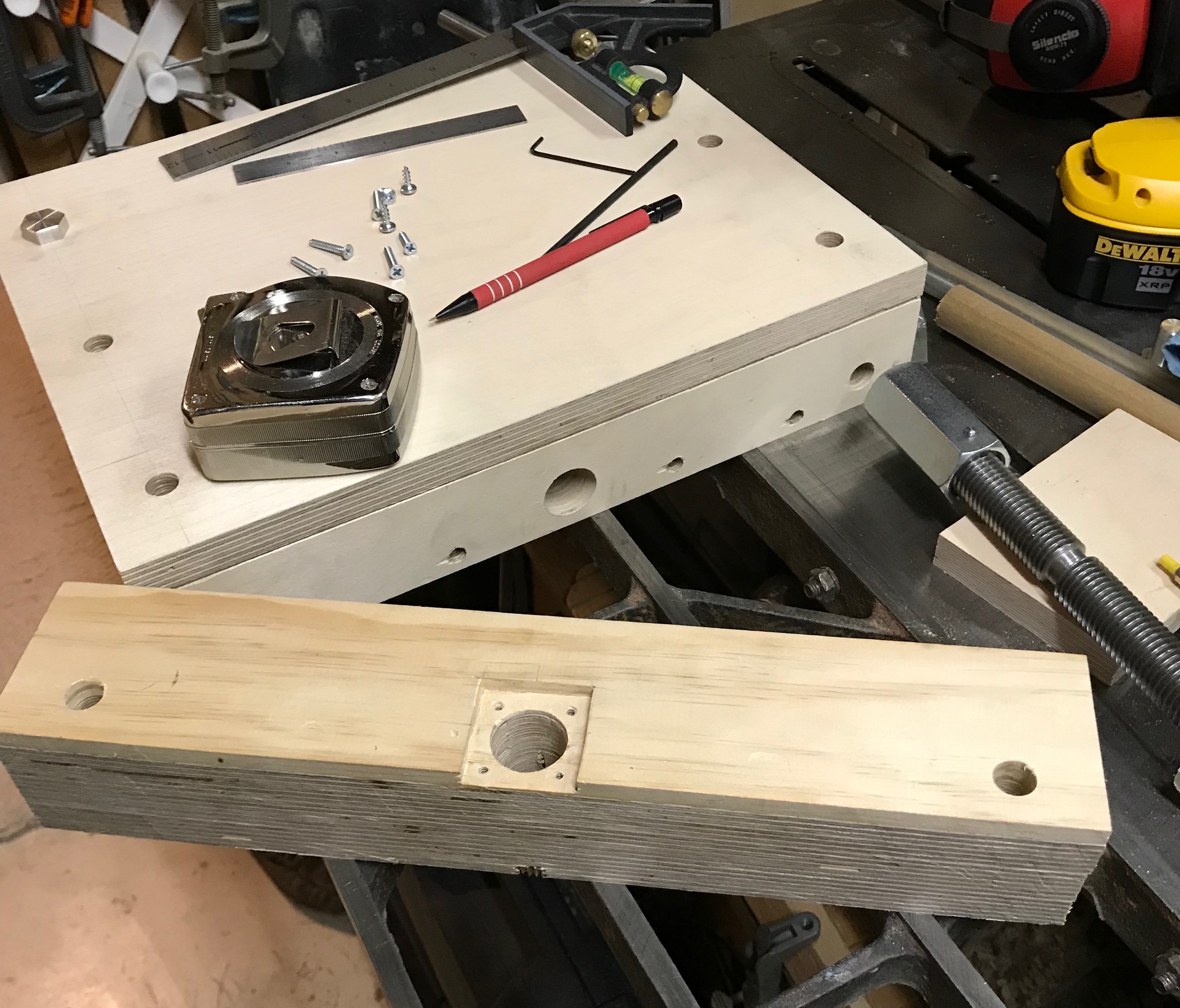
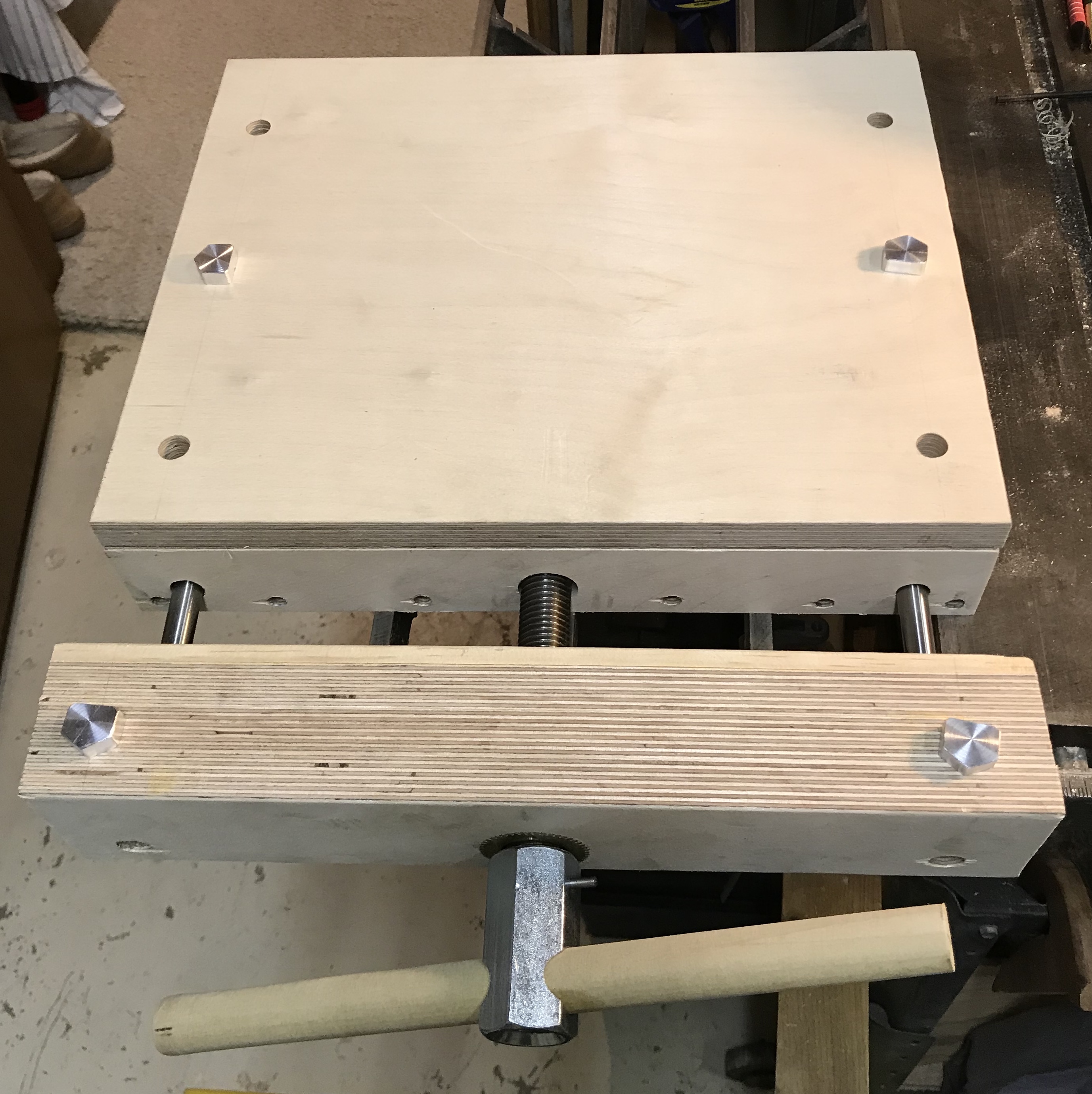
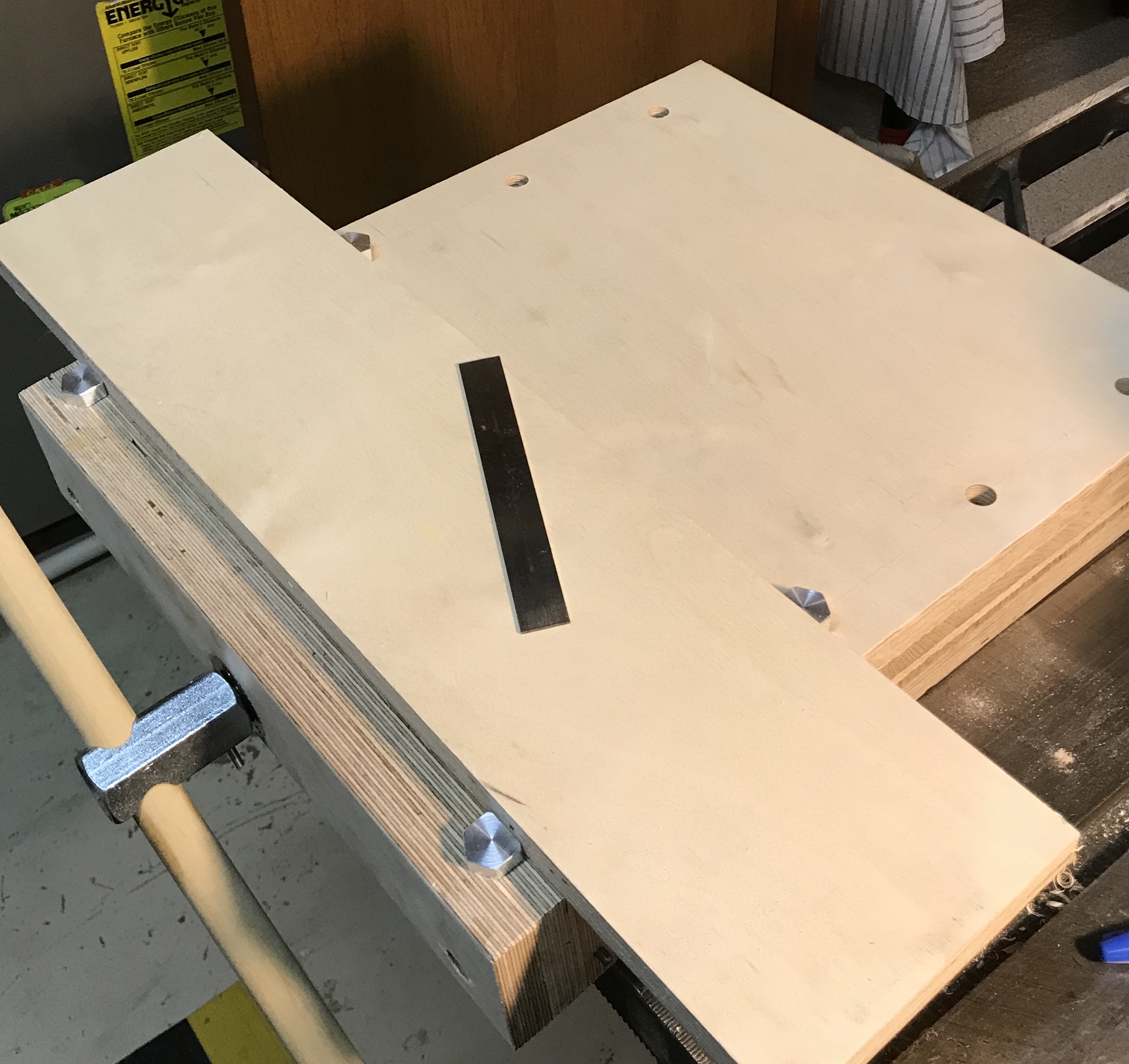
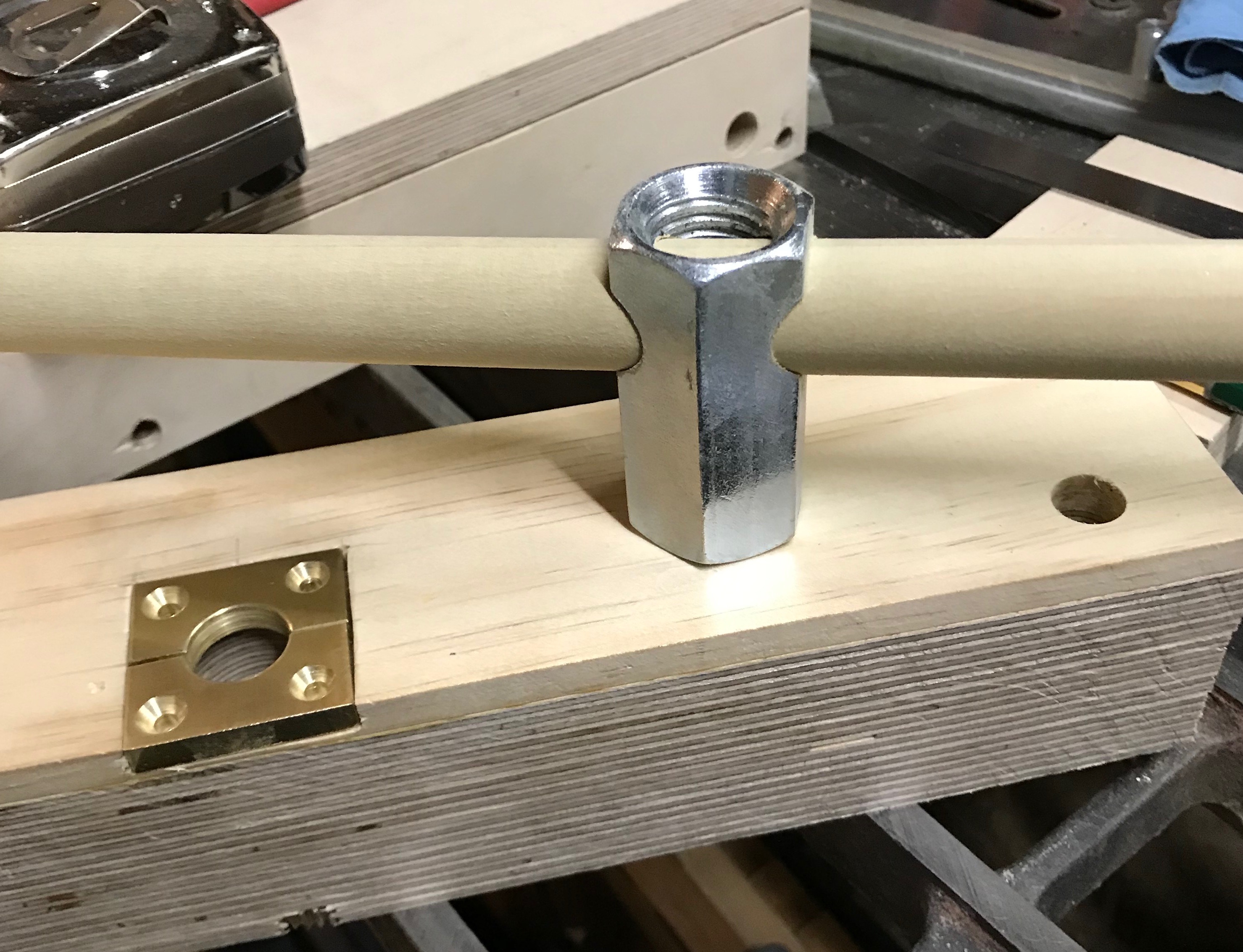
The two pictures above show the pocket for the trapping brass bearing as well as the installed gear bearing. You can also see the groove cut into the screw and the various holes drilled in the fixed jaw.
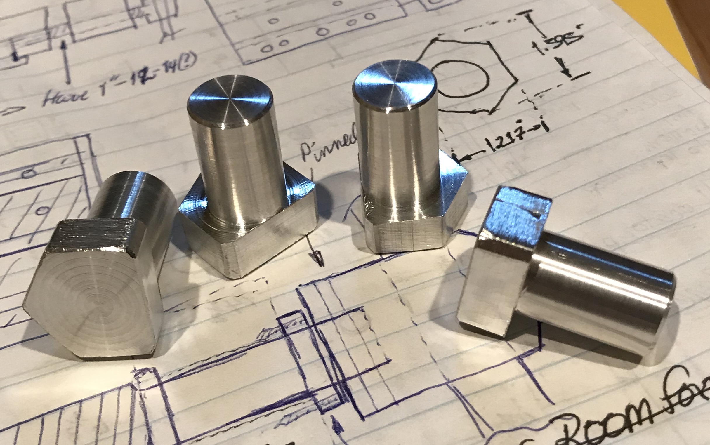
The stops were made from 3/4" aluminum hex. Four 1" lengths were cut off. Both ends were faced and one end was reduced to 1/2" for a length of 3/4". The end was chamferred and the part was deburred. This was repeated to make the four stops. The partially finished version of one of the these can be clearly seen in the upper left corner of the photo above.
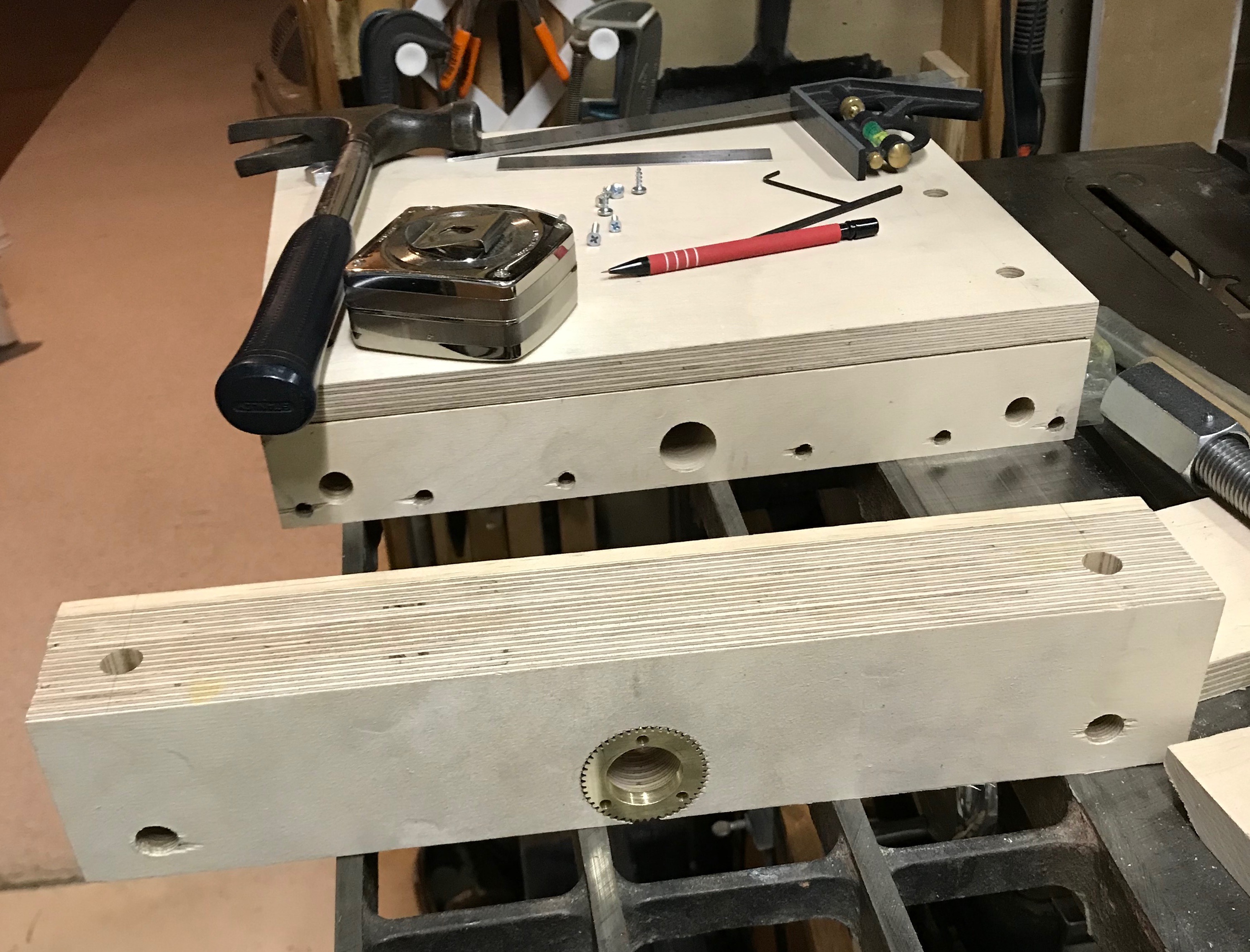
The large connector nut was pinned to the screw. A hole was drilled with a 0.146" drill through the nut and screw. A #2 tapered reamer was then used to ream the desired taper. I reamed too far and the pin drops a little too far into the hole so it will need to be glued in place with Locktite. You can see the screw and nut pinned in the second photo above. The nut was then drilled for the handle. The nut was chucked in the four jaw chuck on the Southbend lathe. The four jaw was adjusted so the center of rotation of the nut was approximately 11/16" from the end and centered on a flat. A center drill was used to begin the hole. This was followed by a 1/4" drill and upward to 7/8" in increments of 1/16". Some of the larger drills are quite dull and need sharpened. After much frustation the hole was completed and deburred with a chamfer bit and a half round file.
The handle began as a 12" length of 7/8" dowel rod. It was chucked in the Sherline lathe and the outboard end held with a live center. (Just pressed it into the wood end). The most effective sandpaper to reduce the diameter was 80-grit. The dowel diameter was reduced to about 0.855". This gave a nice sliding fit in the nut. This is pictured below. In this picture the split bushing can also be seen.
A 3' length of 1/2" drill rod was cut into three pieces with a hacksaw. Two of the pieces were 12 3/4" long. The ends of these two pieces were cleaned up and chamfered with a file. One of these was slid into the left groove and further into the movable jaw. It was left about 1" short of the the front side of the jaw. A hole was drilled with the 0.146" drill at a height of 11/16" and 3/4" in from the closing face of the movable jaw. With the hand drill I could do no more than put a shallow hole into the metal rod. The rod was removed and drilled through on the drill press, while holding the rod in vee blocks. While so held the tapered reamer was used to open the hole to about .165". The hole in the wood was drilled to full depth and reamed. Reinserting the rod allowed the taper pin to be inserted with about 1/8" of pin protruding from the side of the jaw so it can be removed if needed.
Repeating this on the other side ran into a problem. The rod when inserted was a very tight fit. After playing with it a bit the rod moved more freely. It was pinned into place similarly to the first rod. The screw was then attached to the movable jaw with the split bushing. The bushing and the threads of the screw were oiled. Sliding the rods into their respective holes went smoothly, but I could not align the screw with the nut inside to get it started. The top was removed and it was then fairly simple to align and start the screw. After reattaching the top the vise worked perfectly. The screw has too many TPI, but I knew that when I decided to find one for about $10!
The aluminum stops were completed by milling off one corner of the hex. A corner was selected over a face as this led to a slightly longer (~1/8") clamping surface. The stop was placed in the milling vise on the built-in vee. It was held up off the jaws with two drills (removed before cutting) 0.082" & 0.081". A straight edge of the stop was aligned with the front of the vise jaw by eye. About 0.180" needed to be removed. This was done in increments of 0.010" with a 1/2" end mill. The final cut was determined by eye and the edge was left proud of the cylinder by about 0.005". The top corner was chamfered with a file and the bottom edges had burrs removed. The photo below shows the four completed stops.
All that was left was to attach ends to the handle. Two reasonable pieces of scrap were found. A "wheel" was cleaned up in the lathe and attached with a wood screw. A hemisphere had a 1/4" hole part way through so a matching hole was drilled in the end of the handle. A short piece of 1/4" dowel and some glue provided the attachment.